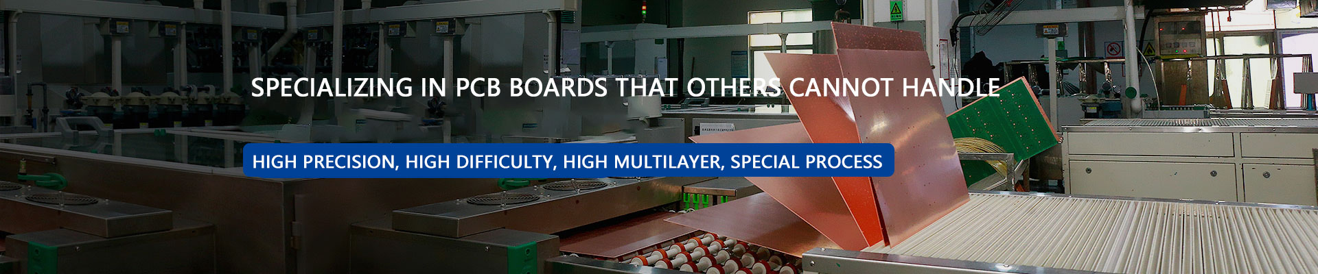
Multi-layer PCB, HDI PCB, Rigid-flex PCB, PCBA factory


At present, the production of circuit boards mostly relies on the subtractive method, which involves subtracting excess copper foil from the raw material copper-clad laminate to form conductive patterns.
Subtractive methods mostly use chemical etching, which is economical and efficient. However, chemical etching attacks indiscriminately, so we need to protect the desired conductive pattern. Then, a layer of resist will be applied to the conductive pattern, and the unprotected copper foil is then etched away. Early resists were created by screen-printing resist ink in the form of circuits, hence the name "printed circuit." However, as electronic products became increasingly sophisticated, the image resolution of printed circuits failed to meet product requirements, leading to the use of photoresists as image resolution materials. Photoresists are photosensitive materials that react photochemically with light of a certain wavelength to form polymers. After selectively exposing the pattern using a pattern film, the unpolymerized photoresist is removed using a developer (e.g., 1% sodium carbonate solution) to form a protective layer.The conduction function between layers is achieved through metallized holes, so drilling operations are required during the PCB production process, and metallization electroplating operations are performed on the holes to finally achieve conduction between layers.

1. First, make two double-sided boards without holes.
Cut the board (DS CCL) - Create the inner layer pattern (form the pattern resist) - Etch the inner layer (remove excess copper foil).
2. Bond and press these two boards together using epoxy resin fiberglass prepreg. The two boards are riveted to the prepreg, and then a copper foil is placed on each side of the outer layer. Pressing is performed under high temperature and high pressure to achieve a bond. The key material is the prepreg, which has the same composition as the original material—epoxy resin fiberglass—but is in an uncured state. It liquefies at temperatures between 7 and 80 degrees Celsius. A curing agent is added to the prepreg, which cross-links with the resin at 150 degrees Celsius to cure, becoming irreversible. This semi-solid-liquid-solid transition achieves bonding under high pressure.
Multi-layer PCB are more complicated than single-layer and 2-layer boards in terms of design and manufacturing. If you are not careful, you will encounter some problems. So what difficulties should we avoid in PCB multi-layer circuit board proofing?
*Difficulties in Interlayer Alignment
Due to the large number of layers in multi layer PCB, users have increasingly stringent requirements for PCB layer alignment. Typically, the alignment tolerance between layers is controlled at 75 microns. This is further complicated by the large unit size of multi layer PCB, the high temperature and humidity in the pattern conversion workshop, the misalignment and overlap caused by the inconsistencies between different core boards, and the interlayer positioning methods.
* Difficulties in Internal Circuit Fabrication
Multi layer PCB utilize specialized materials such as high TG, high speed, high frequency, thick copper, and thin dielectric layers, placing stringent demands on internal circuit fabrication and pattern size control. For example, maintaining impedance and signal transmission integrity complicates internal circuit fabrication. Small widths and line spacing increase the number of opens and shorts, leading to lower yields. The large number of fine-line signal layers increases the probability of leak detection during AOI on inner layers. Thin inner core boards are prone to wrinkling, poor exposure, and curling during etching. High-layer boards are often system boards, with larger unit sizes and high scrap costs.
* Difficulties in Compression Manufacturing
Many core boards and prepreg boards are stacked, making stamping prone to defects such as slippage, delamination, resin voids, and residual bubbles. When designing the laminated structure, the material's heat resistance, pressure resistance, adhesive content, and dielectric thickness must be fully considered to develop a rational material compression plan for multi layer PCB. Due to the large number of layers, expansion and contraction control and dimensional coefficient compensation cannot be consistently maintained, and thin interlayer insulation can easily lead to interlayer reliability test failures.
* Difficulties in Drilling
Using specialized boards with high TG, high speed, high frequency, and thick copper increases the difficulty of drilling roughness, burrs, and drill contamination removal. The large number of layers, combined with the total copper and board thickness, can easily lead to tool breakage during drilling. The densely packed BGAs and narrow hole-to-wall spacing can lead to CAF failures. The board thickness can also easily lead to skew drilling.


 QR code WeChat
 Whatsapp