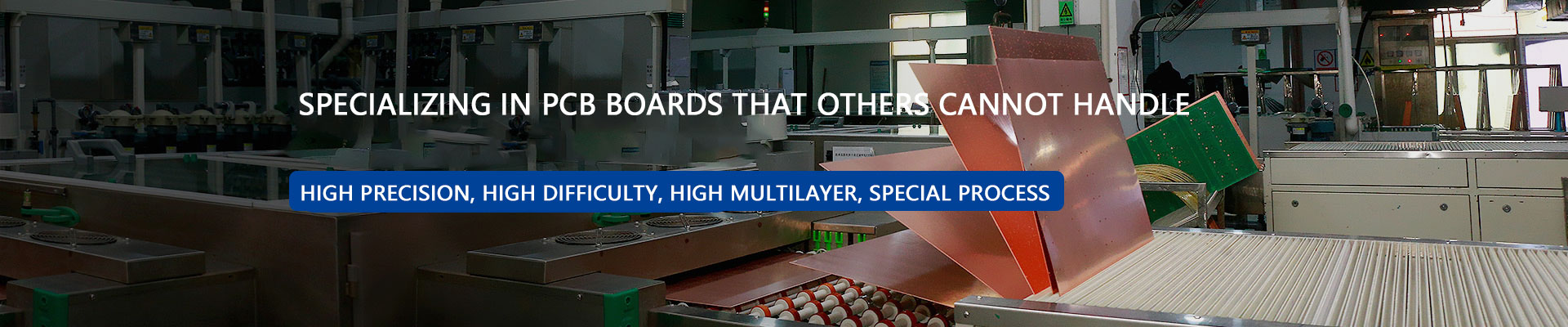
Multi-layer PCB, HDI PCB, Rigid-flex PCB, PCBA factory


While making a multi layer PCB isn't difficult, troubleshooting afterward is challenging. Whether you're a hobbyist or an engineer, encountering problems during PCB debugging can be a real headache, much like a programmer encountering a bug.

Some people have a keen interest in debugging PCB, much like programmers troubleshooting bugs. Common PCB issues are numerous, including board design, damaged electronic components, short circuits, component quality, and broken PCB.
Common PCB failures primarily focus on components like capacitors, resistors, inductors, diodes, transistors, field-effect transistors, and visible damage to integrated circuits and crystal oscillators. Visual inspection is a relatively straightforward way to identify component failures. Visibly damaged electronic components will show obvious burn marks on their surface. These problems can be resolved by simply replacing the problematic component with a new one.
Of course, not all damaged electronic components can be visually detected. For example, the resistors, capacitors, diodes, and transistors mentioned above may not be visible on the surface, requiring specialized inspection tools for repair. Commonly used tools include multimeters and capacitance meters. If the voltage or current of a component is outside the normal range, it indicates a problem with that component or the previous component. Simply replace it and check again to see if it functions properly.
While a damaged component can be detected visually or with an instrument, sometimes when installing components on a PCB, the problem can't be detected, and the board may not function properly. Many novices encounter this problem and are left with no choice but to rebuild or re-build the board. In many cases, this is due to performance instability caused by problems with the coordination of components during installation.
In this case, instruments are no longer helpful. You can try to narrow down the possible fault range based on current and voltage. An experienced engineer may be able to quickly identify the faulty area, but they can't be 100% certain of the specific component that's broken. The only solution is to try replacing suspected components until the problem is found. Last year, my laptop motherboard was flooded. The repairman couldn't pinpoint the fault, and they replaced three components during the repair process: the power supply chip, the diode, and the USB charging component (the blue port on the laptop that allows charging when the laptop is powered off). Finally, after repeated testing and troubleshooting, they finally identified a short circuit in a component near the southbridge chip.
The above examples all involve electronic component issues. Of course, since the PCB is the home of components, PCB faults are inevitable. The simplest example is a dead tinned part. Due to the manufacturing process, the PCB corrodes and breaks can occur. In this case, if patching isn't possible, thin copper flying leads are the only solution.
It is indeed very troublesome to check for PCB circuit board failures when there is no obvious damage. During the troubleshooting process, there will be a sense of concentration, and after finding the problem, there will be an inexplicable sense of accomplishment. This is probably the feeling that programmers have when solving bugs. I often like to troubleshoot some difficult-to-repair boards. This is probably the joy of HDI multi layer board engineers.


 QR code WeChat
 Whatsapp